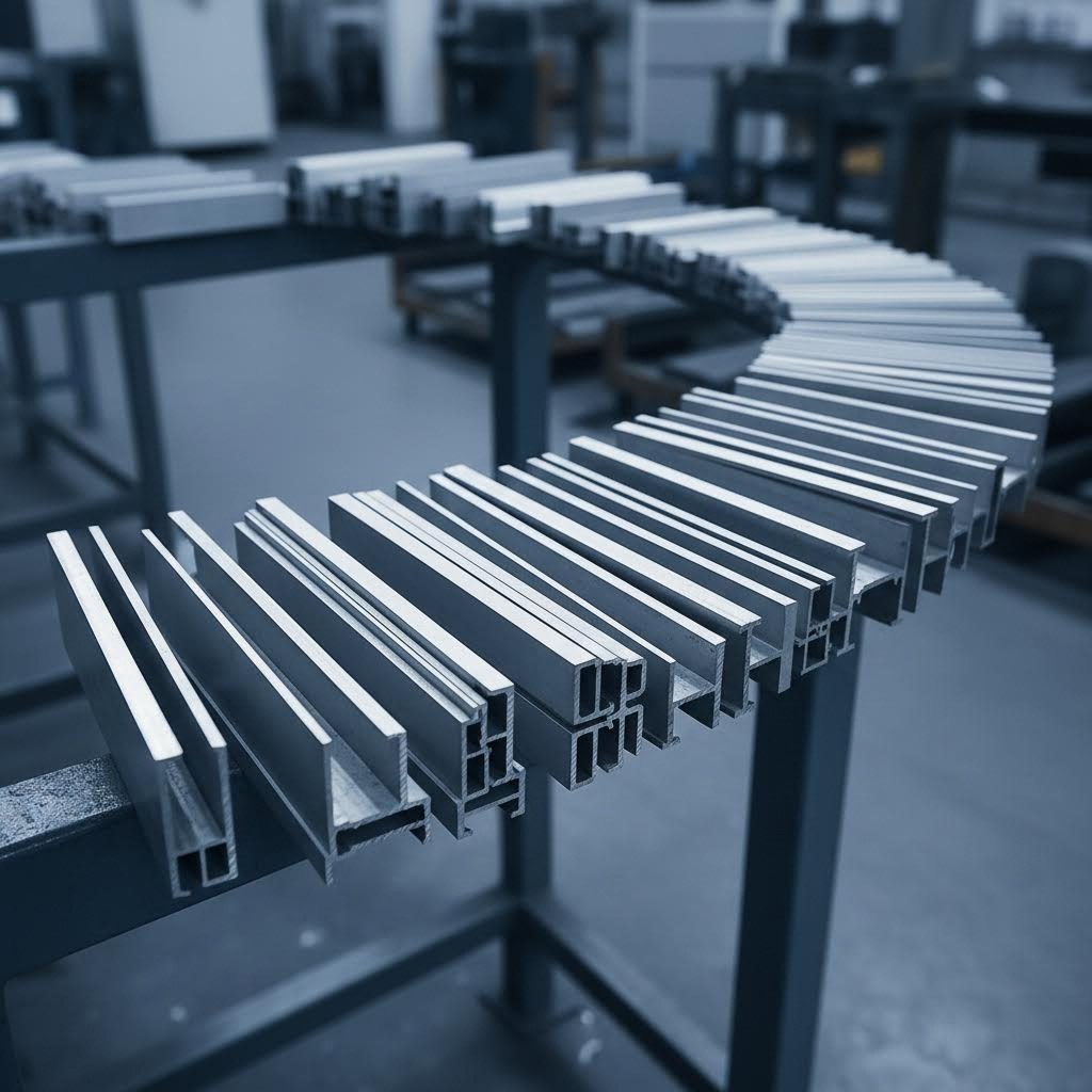
When you're designing an aluminum extrusion profile, every dimension matters. But there's one specification that quietly influences everything from structural performance to your final invoice: wall thickness. Whether you're an engineer refining a prototype or a procurement specialist evaluating quotes, understanding this parameter can mean the difference between a successful project and costly rework.
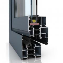
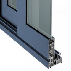
Wall thickness refers to the measurement of material between the inner and outer surfaces of a hollow or semi-hollow aluminum extrusion profile. For solid profiles, it describes the thinnest cross-sectional dimension of any given feature. This seemingly simple measurement directly controls four critical outcomes in your project:
The strength of aluminum extrusions can be tailored by adjusting wall thickness and internal structural profiles, meaning strength can be concentrated precisely where needed without adding unnecessary extra material. This flexibility makes aluminum extrusion a preferred choice across industries, yet many designers overlook how alloy selection and profile geometry constrain their options.
Imagine specifying a wall that's just slightly too thin for your chosen alloy. The result? Production delays, rejected parts, or profiles that warp during cooling. Conversely, over-engineering with unnecessarily thick walls adds weight and material costs that compound across high-volume orders.
Wall thickness decisions ripple through every phase of your project. Getting this specification right from the start protects both your performance requirements and your budget, while getting it wrong creates cascading problems that are expensive to fix downstream.
What makes this topic particularly challenging is that critical data on aluminum extrusion dimensions and tolerances remains scattered across manufacturer specifications, industry standards, and tribal knowledge. Engineers searching for a comprehensive aluminum extrusion design guide often find themselves piecing together information from multiple sources, sometimes encountering inconsistent recommendations along the way.
This article consolidates that fragmented knowledge into one actionable reference. In the sections ahead, you'll discover the manufacturing physics behind minimum thickness limits, alloy-specific capabilities for profiles ranging from 6063 to 6061, shape classification systems that affect your options, and tolerance standards that impact assembly fit. You'll also learn practical guidance on cost optimization and how to communicate specifications effectively when requesting quotes. Whether you're troubleshooting an aluminum extrution issue or exploring what is aluminum extrusions for the first time, this guide provides the technical depth and practical insights you need to make informed decisions.
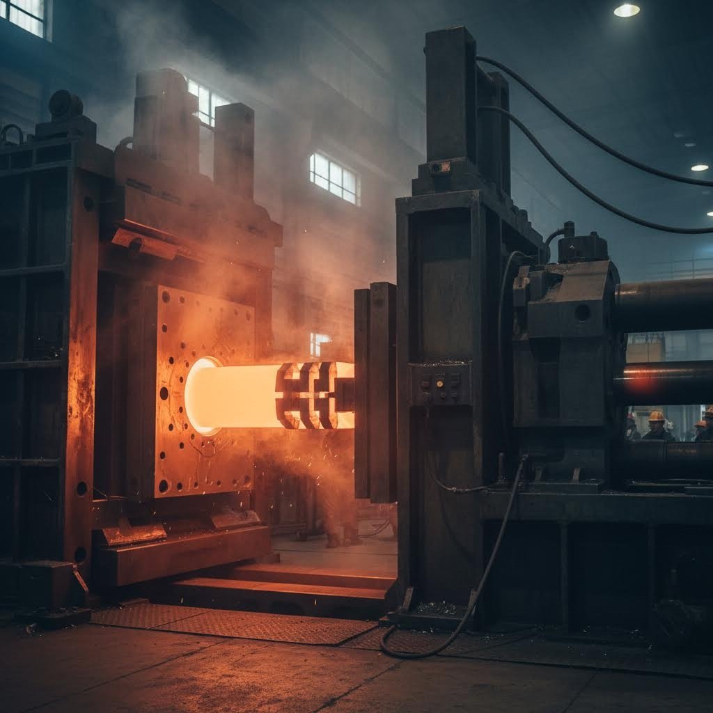
You've probably encountered specifications stating that a 5-inch circumscribing circle requires a minimum wall thickness of 0.040 inches, or that hollow profiles need thicker walls than solid shapes. But have you ever wondered why these limits exist? Understanding the physics behind aluminum extrusion reveals why certain wall thicknesses simply cannot be achieved, no matter how precisely you specify them on a drawing.
Picture a hydraulic ram forcing a heated aluminum billet through a precisely shaped die opening. This process, known as al extrusion, transforms solid cylindrical billets into complex cross-sectional profiles in a single operation. The magic happens at temperatures between 375°C and 500°C, where aluminum becomes soft enough to flow plastically yet maintains enough structure to hold its shape upon cooling.
When you extrude aluminum through a die, the material behaves similarly to a highly viscous fluid under extreme pressure. According to COMSOL's fluid-structure interaction research, this approach treats the aluminum as a non-Newtonian fluid with viscosity that depends on both velocity and temperature. Internal friction within the flowing metal generates heat, creating a fully coupled thermal-mechanical system where every variable influences the others.
Here's where wall thickness constraints emerge. As aluminum flows through narrow die passages, friction against the die walls increases dramatically. Thinner wall sections create higher resistance to metal flow, requiring greater pressure to push material through. At some point, the required pressure exceeds practical limits, or the flow becomes so restricted that the profile exits with incomplete sections, surface defects, or internal voids.
The relationship between profile size and achievable wall thickness follows predictable patterns rooted in metal flow dynamics. The circumscribing circle, which is the smallest circle that can completely enclose your profile's cross-section, serves as the primary reference point. This measurement determines which press size you'll need and establishes the baseline for minimum wall requirements.
Why does the circumscribing circle matter so much? Larger profiles require bigger billets, which means more material must flow through the die simultaneously. As industry research indicates, there's a linear relationship between circumscribing circle diameter and minimum achievable wall thickness for any given alloy. Small specialty profiles with 30mm circumscribing circles can achieve walls as thin as 0.3mm, while large railway profiles with 600mm circles require minimum thicknesses of 7-8mm for simple tubes, or 2.7-3mm for complex multi-chamber sections.
The extrusion ratio, defined as the billet cross-sectional area divided by the profile area, further constrains your options. Ratios that are too low provide insufficient material reduction, while extremely high ratios demand excessive force. For softer 6xxx alloys, practical ratios range from 10 to 100, whereas harder alloys like 2xxx and 7xxx series are limited to ratios between 10 and 35.
Multiple variables interact to determine the thinnest wall your alumnium extrusion can achieve:
These factors don't operate in isolation. The interplay between them explains why experienced extruders evaluate each profile individually rather than applying universal minimum thickness rules. A wall thickness that works perfectly for a simple rectangular tube might fail completely when applied to a complex multi-chamber profile in the same alloy and circumscribing circle.
Understanding these physics helps you approach suppliers with realistic expectations. When you specify wall dimensions at the edge of what's achievable, you're essentially asking the manufacturer to push against fundamental material behavior limits. The next section explores how different alloys respond to these constraints, giving you the data needed to select materials that match your thickness requirements.
Now that you understand why wall thickness limits exist, the next question becomes: which alloy gives you the thinnest walls while meeting your structural requirements? This is where many engineers and procurement professionals encounter frustrating gaps in available information. Specifications are scattered across manufacturer datasheets, and direct alloy-to-alloy comparisons remain surprisingly hard to find.
The truth is that your alloy choice fundamentally constrains what wall dimensions are achievable. Select the wrong material for your aluminum extrusion profiles, and you'll face either production failures or unnecessarily thick walls that add weight and cost. Let's consolidate the data you need into one actionable reference.
Different aluminum extrusion alloys behave very differently as they flow through dies. The key factor is extrudability, which measures how easily an alloy can be pushed through complex die geometries at production speeds. According to industry extrudability research, alloy 6063 serves as the benchmark with an extrudability index of 100. Every other alloy is rated relative to this standard, with higher numbers indicating greater extrusion difficulty.
Why does extrudability matter for wall thickness? Alloys that flow more easily require less pressure to fill thin die passages completely. This means they can achieve thinner walls without defects like incomplete sections, surface tearing, or internal voids. The relationship between flow stress and achievable wall thickness is well-documented across aluminum profiles extrusion applications.
| Alloy | Extrudability Index | Typical Minimum Wall (inches) | Recommended Wall Range (inches) | Tolerance Class | Best Applications |
|---|---|---|---|---|---|
| 6063 | 100 (baseline) | 0.040 | 0.040 - 0.500 | Tighter tolerances achievable | Architectural, decorative, heat sinks, complex shapes |
| 6060 | ~100 | 0.040 | 0.045 - 0.500 | Tighter tolerances achievable | Architectural, furniture, general fabrication |
| 6463 | ~100 | 0.040 | 0.045 - 0.500 | Tighter tolerances achievable | Bright finish applications, anodized trim |
| 6005/6005A | ~120 | 0.050 | 0.062 - 0.625 | Standard tolerances | Structural, transportation, ladders |
| 6105 | ~120 | 0.050 | 0.062 - 0.500 | Standard tolerances | Structural frames, moderate stress applications |
| 6061 | ~160 | 0.062 | 0.078 - 0.750 | Wider tolerances typical | Structural, marine, aerospace, high-stress components |
| 6351 | ~140 | 0.055 | 0.070 - 0.625 | Standard tolerances | Piping, structural tubing, high-strength applications |
| 6082 | ~180 | 0.078 | 0.094 - 1.000 | Wider tolerances typical | Heavy structural, bridges, cranes, offshore |
Notice the pattern? As extrudability index increases, minimum achievable wall thickness also increases. This isn't coincidental. Alloys with higher silicon and magnesium content develop greater flow stress at extrusion temperatures, making them harder to push through tight die passages. The Bonnell Aluminum design guidelines confirm that 6063 alloy is typically used in moderate stress applications precisely because its superior extrudability enables thinner walls and more complex geometries.
Selecting an alloy based solely on minimum wall capability would be a mistake. You need to balance extrudability against the mechanical properties your application demands. Here's how to think through this decision:
When 6063 is your best choice:
When 6061 makes more sense:
The extruded aluminum profile you ultimately produce depends heavily on matching alloy capabilities to your actual requirements. According to aluminum extrusion alloy selection research, complex geometries and thin walls specifically require alloys like 6063 or 6360 to ensure uniform shapes and minimize distortion.
Consider this practical example: You're designing a heat sink with intricate fin geometry requiring 0.045-inch wall sections. Choosing 6061 because you're familiar with it from structural work would likely result in production problems. The alloy simply doesn't flow well enough into those thin passages at economical production speeds. Meanwhile, 6063-T5 would handle this geometry easily while still providing adequate thermal conductivity and mechanical support.
Conversely, specifying 6063 for a load-bearing structural member just to achieve thinner walls could compromise safety margins. In this case, 6061's higher yield strength (35 ksi versus 25 ksi in T6 temper) justifies accepting slightly thicker walls.
The aluminium extrusion types available extend beyond just 6063 and 6061. Intermediate options like 6005A offer a middle ground with better extrudability than 6061 while providing higher strength than 6063. This alloy works well when you need walls in the 0.050 to 0.125-inch range with enhanced structural performance.
Temperature and temper also influence your options. The mechanical properties table from Bonnell Aluminum specifications shows that wall thickness requirements vary even within a single alloy depending on temper designation. For example, 6063-T5 with walls up to 0.500 inches delivers 22 ksi ultimate tensile strength, while the same alloy in T6 temper achieves 30 ksi but with slightly different processing requirements.
Before finalizing your alloy selection, ask yourself these questions: What's the thinnest wall section in my design? What are my actual strength requirements versus my assumed requirements? How complex is my profile geometry? The answers will guide you toward the right balance between extrudability and performance, ensuring your extruded aluminum profiles meet both manufacturing feasibility and application demands.
You've selected your alloy and understand the physics behind extrusion limits. But here's where many engineers get tripped up: the same alloy with identical wall thickness specifications can succeed or fail depending entirely on profile shape. A 0.050-inch wall that extrudes perfectly in a solid bar might cause production nightmares in a complex hollow section.
The aluminum extrusion industry classifies shapes into distinct categories, each with its own wall thickness rules. Understanding these classifications helps you predict manufacturing feasibility before your design ever reaches a quote request. Let's break down what shapes you can actually achieve and the wall constraints that come with each.
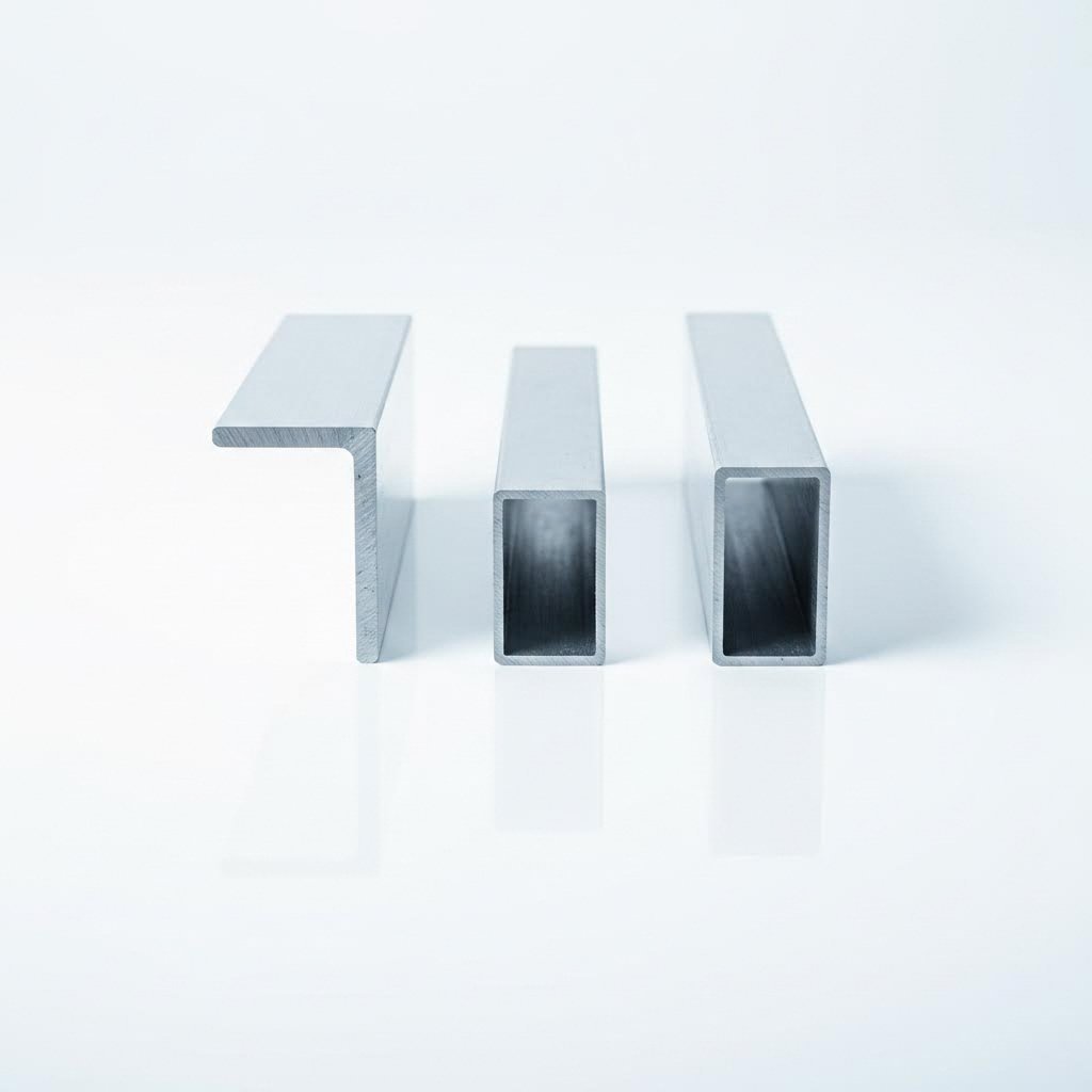
Every extruded aluminum shape falls into one of three fundamental categories: solid, semihollow, or hollow. This classification isn't arbitrary—it reflects how dies are constructed and how metal flows during extrusion.
Solid shapes are the simplest to produce. These profiles contain no enclosed voids and include angles, channels, flat bars, and complex open sections. Because the die consists of a single piece with no internal supports, metal flows relatively uniformly through the opening. This simplicity translates directly into thinner achievable walls.
Semihollow shapes partially enclose a void, like a C-channel with a narrow gap or a track with an undercut. The die requires a tongue or finger extending into the opening, and this unsupported section creates manufacturing challenges. The tongue must withstand tremendous pressure without deflecting, limiting how deep and narrow the enclosed area can be.
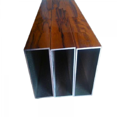
Hollow shapes completely enclose one or more voids—think rectangular tubes, round pipes, or multi-chamber profiles. These require bridge or porthole dies where metal splits around internal supports and rewelds downstream. The rewelding process demands additional pressure and careful temperature control, directly impacting minimum wall requirements.
| Shape Category | Description | Minimum Wall Thickness Range (inches) | Tolerance Expectations | Die Complexity |
|---|---|---|---|---|
| Solid | No enclosed voids; includes angles, bars, channels, T-sections | 0.040 - 0.062 | Tightest tolerances achievable; ±0.004" to ±0.012" typical | Lowest; single-piece flat die |
| Semihollow Class 1 | Partially enclosed void symmetrical about gap centerline | 0.040 - 0.078 | Standard tolerances; slightly wider than solid | Moderate; requires tongue in die |
| Semihollow Class 2 | Partially enclosed void asymmetrical or unequal wall thicknesses | 0.050 - 0.094 | Standard to wider tolerances | Higher; asymmetric tongue stress |
| Hollow Class 1 | Single round void ≥1" diameter, symmetrical about two or more axes | 0.055 - 0.110 | Standard tube tolerances apply | Moderate; balanced bridge die |
| Hollow Class 2 | Single void ≥0.375" diameter within 5" circumscribing circle, not Class 1 | 0.062 - 0.140 | Wider tolerances typical; wall eccentricity considerations | Higher; unbalanced metal flow |
| Hollow Class 3 | Multiple voids or shapes not meeting Class 1 or 2 criteria | 0.078 - 0.188+ | Widest tolerances; subject to negotiation | Highest; complex bridge configurations |
The Bonnell Aluminum classification system establishes these categories based on specific geometric criteria. Class 1 hollow shapes, for instance, must have a round internal void at least one inch in diameter with the shape symmetrically balanced around that void by two or more axes. This symmetry enables balanced metal flow during extrusion, permitting thinner walls than asymmetric designs.
Beyond basic classification, the geometry within each category significantly impacts achievable wall thickness. Two hollow profiles in the same class can have dramatically different minimum wall requirements based on their specific features.
The gap ratio calculation determines whether a partially enclosed void qualifies as semihollow or gets reclassified as hollow. This ratio equals the area of the enclosed void (B) divided by the square of the gap width (A). According to Australian Aluminium Council specifications, the threshold varies by gap width:
Why does this matter for wall thickness? If your design accidentally crosses from semihollow into hollow classification, minimum wall requirements jump significantly. A small geometry change—narrowing a gap by 0.020 inches—could push your gap ratio over the threshold, suddenly requiring thicker walls throughout the profile to ensure successful extrusion.
Each shape category demands specific attention to wall thickness distribution and geometry:
For solid shapes:
For semihollow shapes:
For hollow shapes:
The circumscribing circle relationship applies differently across shape categories. According to industry reference charts, a profile with a 4-5 inch circumscribing circle requires minimum walls of 0.062 inches for solids and semihollows, but 0.094 inches for Class 2 hollows. That 50% increase reflects the additional manufacturing challenges hollow shapes present.
Here's a practical example: You're designing a rectangular tube with 2-inch by 3-inch outside dimensions. As a Class 2 hollow with roughly a 3.6-inch circumscribing circle, minimum wall thickness would be approximately 0.078 inches in 6063 alloy. But if you could redesign this as a C-channel with a 0.5-inch gap (making it semihollow), minimum walls drop to around 0.050 inches. That 35% reduction in wall thickness translates to meaningful weight and material savings across production volumes.
The key insight competitors often miss is that classification boundaries aren't fixed constraints—they're design variables. By understanding gap ratio thresholds and shape category implications, you can sometimes modify geometry slightly to shift into a more favorable classification, achieving thinner walls without compromising function. This strategic approach to aluminum extrusion shapes separates cost-optimized designs from those that simply meet minimum requirements.
With shape classifications clarified, the next critical factor is understanding exactly how much variation you can expect in your specified wall dimensions. Tolerance standards determine whether your extruded shapes will actually fit together in assembly—and that's where many projects encounter unexpected challenges.
You've specified a 0.125-inch wall thickness on your drawing. But when the extrusions arrive, will they actually measure 0.125 inches? The honest answer is: probably not exactly. Every aluminum extrusion tolerances specification includes an allowable deviation range, and understanding these ranges before you finalize your design prevents assembly headaches downstream.
The challenge is that tolerance data remains frustratingly scattered. Industry standards like those published in the Aluminum Association tolerance tables contain the authoritative numbers, but interpreting what those numbers mean for your specific application requires context that raw data tables don't provide. Let's consolidate the critical tolerance information and translate it into practical guidance.
Wall thickness tolerances for standard aluminum extrusions follow predictable patterns based on the nominal dimension and profile classification. According to Aluminum Association Table 11.2, metal dimension tolerances apply when 75 percent or more of the dimension consists of aluminum material. The following table consolidates the key tolerance values you'll encounter most frequently:
| Specified Wall Thickness (inches) | Standard Tolerance (± inches) | Precision Tolerance (± inches) | Practical Interpretation |
|---|---|---|---|
| Up through 0.124 | 0.006 | 0.004 | Actual wall may range from 0.118" to 0.130" at standard tolerance |
| 0.125 - 0.249 | 0.007 | 0.005 | A 0.125" wall could measure 0.118" to 0.132" at standard tolerance |
| 0.250 - 0.499 | 0.008 | 0.005 | Quarter-inch walls allow roughly 3% variation at standard tolerance |
| 0.500 - 0.749 | 0.009 | 0.006 | Half-inch walls permit less than 2% variation |
| 0.750 - 0.999 | 0.010 | 0.007 | Thicker walls maintain tighter percentage variation |
| 1.000 - 1.499 | 0.012 | 0.008 | One-inch walls allow roughly 1.2% variation |
| 1.500 - 1.999 | 0.014 | 0.009 | Less than 1% variation for heavy-wall sections |
These values apply to circumscribing circles less than 10 inches in diameter. For larger profiles, tolerances increase. A 15mm aluminum extrusion wall (approximately 0.590 inches) would fall in the 0.500-0.749 range, giving you ±0.009 inches standard tolerance or roughly ±0.23mm in metric terms.
Hollow profiles introduce additional considerations. According to the MK Metal specifications, wall thickness tolerances for hollow sections enclosing space of 0.11 square inches or more follow eccentricity rules rather than simple plus-minus values. The allowable deviation ranges from 10% of specified dimension (minimum 0.010 inches) to 15% (maximum 0.060 inches for standard, 0.090 inches for larger circles).
Sounds complex? Here's what these numbers actually mean for your assembly. When you specify a 0.125-inch wall and receive profiles at ±0.007 inches standard tolerance, any individual measurement could legitimately fall between 0.118 and 0.132 inches. That 0.014-inch total variation seems small until you're trying to fit mating parts together.
Consider a practical scenario: You're designing an interference fit where a component slides into an extruded channel. If your channel's internal dimension has ±0.007-inch tolerance and your insert has similar tolerance, the worst-case stack-up is 0.028 inches. Your "precision fit" could end up either impossibly tight or unacceptably loose depending on which end of the tolerance range each part lands.
The tolerance value itself is only half the story. Understanding how tolerances stack across multiple mating surfaces determines whether your assembly actually works in production, not just on paper.
Precision tolerances, as detailed in the Alumaster technical guide, reduce these variations significantly but come with cost implications. Achieving ±0.005 inches instead of ±0.008 inches on a quarter-inch wall requires slower extrusion speeds, more careful temperature control, and increased inspection. Expect cost premiums of 30% to 200% depending on the tightness required.
After reviewing hundreds of specifications, certain patterns emerge in how tolerance problems develop:
The Keymark tolerance documentation notes that tolerances for dimensions composed of two or more component dimensions equal the sum of the individual tolerances. This additive relationship explains why complex profiles with multiple thin walls often require precision tolerances on critical features even when standard tolerances would suffice for simpler shapes.
Understanding these tolerance relationships helps you design assemblies that work reliably across the full range of acceptable extruded aluminum sizes. But tolerances aren't the only factor affecting your project economics. The next consideration is how your wall thickness choices directly impact tooling costs, production efficiency, and ultimately your per-piece pricing.
You've selected your alloy, classified your profile shape, and defined your tolerance requirements. Now comes the question that procurement teams ask first but engineers often consider last: what does this actually cost? The relationship between wall thickness and project economics runs deeper than simple material weight calculations. Your thickness choices directly influence die longevity, production yields, and downstream processing requirements in ways that compound across production volumes.
Here's what many specifications overlook: pushing toward minimum achievable wall thickness isn't always the most economical choice. Sometimes, adding a few thousandths of an inch to your walls reduces total project cost by improving production stability and extending tooling life. Let's examine the cost factors that should inform your aluminum extrusion design decisions.
Raw material expenses typically account for approximately 90% of basic extrusion costs according to industry cost analysis. This makes thinner walls appear attractive at first glance—less aluminum per foot means lower material spend. But production economics tell a more nuanced story.
When you specify walls at or near minimum achievable thickness, several cost multipliers activate simultaneously:
The aluminum extrusion design guidelines from experienced manufacturers consistently emphasize that optimal wall thickness balances weight reduction against manufacturing stability. According to wall thickness optimization research, maintaining uniform wall thickness throughout your profile helps material move smoothly through the die, keeps surfaces consistent, and enables faster production with better dimensional control.
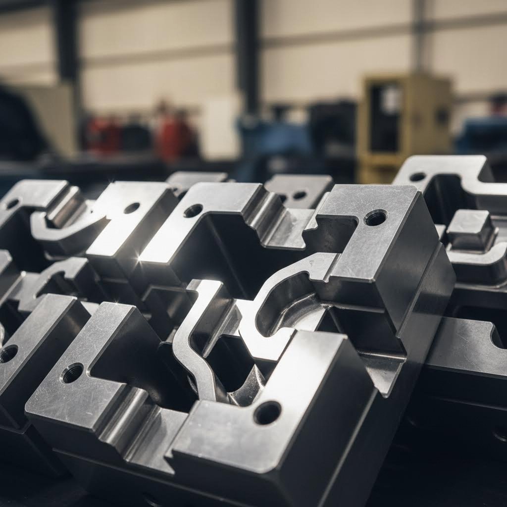
Die replacement represents a significant ongoing cost that thin-wall specifications accelerate. A comprehensive study of 616 die failures referenced in aluminum extrusion design analysis reveals how die construction directly impacts production economics.
Thin-wall profiles stress dies disproportionately. The narrow passages require higher extrusion pressures to achieve complete fill, and this increased pressure accelerates wear on bearing surfaces. Die life depends on:
Proper die design optimization extends service life and reduces maintenance requirements according to aluminium extrusion design guidelines. When specifying thin walls, discuss expected die life with your supplier and factor replacement costs into total project economics.
The sweet spot exists where weight reduction benefits intersect with stable, economical production. Consider these decision factors:
When thin-wall extrusions make economic sense:
When standard or thicker walls prove more economical:
According to manufacturing limit analysis, extrusion presses, dies, and cooling systems have inherent limits. Thin designs slow production and raise scrap rates, increasing price per kilogram. At some point, lighter profiles cost more, not less. Smart aluminum extrusion design stops where total cost is lowest, not where weight is lowest.
The practical approach involves requesting quotes at multiple wall thickness specifications. A 0.078-inch wall might cost 15% less per piece than 0.062-inch despite using slightly more material. Understanding how to cut aluminum extrusion efficiently also factors into this equation—thicker walls often permit faster cutting speeds and longer tool life in downstream fabrication.
With cost and die life factors understood, the next step is translating your technical requirements into specifications that suppliers can accurately quote. Clear communication prevents the misunderstandings that lead to rejected quotes, production problems, and project delays.
You've done the engineering work. You understand your alloy options, profile classifications, tolerance implications, and cost factors. Now comes the moment where all that knowledge either translates into a successful project or gets lost in communication gaps with your supplier. The difference between a smooth production run and months of frustrating back-and-forth often comes down to how clearly you specify your requirements upfront.
Surprisingly, practical guidance on communicating aluminum profile extrusion specifications remains one of the biggest gaps in available resources. Engineers know what they need but struggle to express it in terms suppliers can act on. Procurement teams receive quotes that don't match expectations because critical details were assumed rather than stated. Let's fix that with a systematic approach to specification and supplier evaluation.
When you submit a request for quote, incomplete information triggers one of two outcomes: either the supplier makes assumptions that may not match your intent, or they return clarifying questions that delay your timeline. Neither serves your project well. Include these elements in every quote request to get accurate pricing and prevent downstream issues:
Missing even one of these elements creates ambiguity. A supplier receiving a drawing with wall thicknesses shown but no tolerance callouts must guess whether you expect standard industry tolerances or tighter precision values—a difference that can change quoted pricing by 30% or more.
Beyond listing requirements, how you communicate them affects supplier response quality. Consider these common specification mistakes that lead to rejected quotes or production issues:
Over-specifying tolerances: According to manufacturing design analysis, unrealistic tolerance specifications increase manufacturing complexity and costs significantly. Standard extrusion processes achieve tolerance ranges between ±0.2mm to ±0.5mm depending on geometry complexity. Specifying tighter tolerances requires secondary operations like CNC machining that can double production costs. Only call out precision tolerances where function actually demands them.
Ignoring wall thickness transitions: Abrupt changes in wall thickness create weak points and cooling rate differences that cause warping. Design experts recommend maintaining uniform thickness whenever possible and transitioning gradually where variation is necessary. If your design requires thickness changes, discuss feasibility with your supplier before finalizing specifications.
Assuming standard alloys when alternatives might work better: Many engineers default to familiar alluminum extrusions in 6061 when 6063 would achieve thinner walls more economically. Conversely, specifying 6063 for high-stress applications may force unnecessarily thick walls to compensate for lower strength. Ask suppliers which alloy they recommend for your specific geometry and performance requirements.
Neglecting assembly integration: According to extrusion design research, designing parts without considering assembly requirements creates expensive complications during production. Mechanical fasteners need adequate material thickness and proper access clearances. If your aluminum extrusion assembly requires welding, snap-fits, or fasteners, specify these requirements so suppliers can evaluate wall thickness adequacy.
Providing incomplete surface specifications: A drawing that shows wall thickness but doesn't indicate which surfaces are cosmetically critical leaves suppliers guessing about die polishing requirements and handling procedures. Mark critical surfaces explicitly and specify acceptable defect levels for each.
Not every extruder can achieve every wall thickness specification. According to aluminum supplier selection guidance, evaluating production scale and technical capability determines whether a supplier can reliably deliver your precision aluminum products. Key questions to ask include:
Before committing to production volumes, request physical samples to validate extrusion precision, surface finish, and material consistency. Best practices recommend asking for quality certificates, audit reports, or production videos to verify capabilities match claims.
The specification process isn't just about documenting requirements—it's about establishing clear communication that prevents costly misunderstandings. When suppliers understand exactly what you need, they can provide accurate quotes, realistic timelines, and reliable production. With your specifications clearly communicated and supplier capabilities verified, the final step is matching your wall thickness decisions to your specific application requirements.
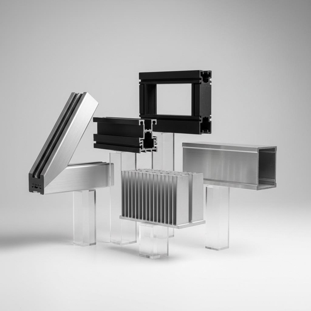
Your wall thickness specification ultimately serves one purpose: ensuring your extruded profile performs reliably in its intended application. All the alloy data, tolerance tables, and cost calculations converge here, where theoretical capabilities meet real-world demands. The challenge is that different applications prioritize competing factors—weight reduction matters enormously in transportation but barely registers for stationary industrial equipment. Structural loads that would crush thin-wall architectural trim pose no threat to heavy-duty framing members.
Understanding what are aluminum extrusions used for across different industries helps you calibrate your thickness decisions appropriately. Let's examine how application requirements should drive your wall thickness specifications.
Each application category balances load capacity, weight constraints, durability expectations, and assembly methods differently. According to industry application research, these varying priorities create distinct thickness ranges that have proven successful across thousands of production projects.
| Application Category | Recommended Wall Thickness Range | Primary Considerations | Common Profile Types |
|---|---|---|---|
| Architectural | 1.2mm - 2.0mm (0.047" - 0.079") | Appearance, corrosion resistance, system compatibility, thermal performance | Window frames, curtain walls, door systems, decorative trim |
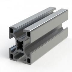
| Industrial/Framing | 1.8mm - 3.5mm (0.071" - 0.138") | Rigidity, fastener engagement, repeatability, modular assembly | T-slot framing, machine guards, conveyor structures, workstations |
| Structural/Load-Bearing | 2.5mm - 6.0mm+ (0.098" - 0.236"+) | Load capacity, safety factors, deflection limits, connection strength | Bridge components, vehicle chassis, crane structures, heavy equipment |
| Heat Sink/Thermal | 1.0mm - 2.5mm (0.039" - 0.098") | Surface area maximization, fin density, thermal conductivity, weight | Electronics enclosures, LED housings, power electronics cooling |
| Transportation | 1.5mm - 4.0mm (0.059" - 0.157") | Weight optimization, crash performance, fatigue resistance, integration | Vehicle body panels, rail car structures, aerospace components |
| Renewable Energy | 1.8mm - 3.0mm (0.071" - 0.118") | Outdoor durability, installation speed, long-term corrosion resistance | Solar panel frames, mounting rails, wind turbine components |
Notice how these ranges overlap significantly. A 2.0mm wall could serve architectural, industrial, or renewable energy applications depending on other design factors. The extruded profile geometry, alloy selection, and specific loading conditions refine these general ranges into precise specifications.
When structural integrity drives your design, wall thickness becomes a direct input to load capacity calculations. But thicker isn't automatically better. According to aluminum extrusion design research, the intended application plays a significant role in determining wall thickness requirements—profiles used in load-bearing applications require thicker walls compared to those used for decorative purposes.
The relationship between wall thickness and structural performance follows predictable engineering principles. For extruded structural aluminum sections under bending loads, moment of inertia increases with wall thickness, but so does weight. The optimization question becomes: what's the minimum wall that meets your deflection and stress requirements with appropriate safety margins?
Balancing weight reduction against load-bearing requirements:
According to thickness optimization research, standard practice is to thicken only where load or machining requires it, not everywhere. Going thicker than needed doesn't always improve performance and can actually cause production issues like uneven cooling, sink marks, and dimensional instability.
Before finalizing your wall thickness specification for any aluminum extrusion applications, work through these evaluation questions:
The thin-wall trend continues gaining momentum across industries seeking weight reduction and material efficiency. Extrusions aluminum manufacturers have responded with improved die technology and process control that enable walls previously considered impractical. However, this capability doesn't mean thin walls are always the right choice.
When thicker walls remain the better choice:
The key insight is that optimal wall thickness emerges from application-specific analysis, not generic guidelines. A 1.5mm wall that performs perfectly in one context might fail in another with identical load requirements but different connection methods, environmental exposure, or quality expectations.
With application requirements clarified and your wall thickness decisions grounded in real performance needs, you're ready to synthesize everything into a coherent decision framework that guides your projects from concept through production.
You've now explored the complete landscape of aluminum extrusion wall thickness, from the physics constraining minimum dimensions to the cost factors that shape project economics. The question remaining is: how do you translate all this knowledge into confident, actionable decisions for your specific projects?
The reality is that wall thickness optimization isn't about finding a single "correct" answer. It's about systematically evaluating tradeoffs until you reach a specification that satisfies your technical requirements, manufacturing feasibility, and budget constraints simultaneously. Let's consolidate everything into a practical framework you can apply immediately.
Whether you're designing aluminum extruded profiles for architectural systems or complex industrial applications, this six-step process ensures you address every critical factor before committing to production:
The most successful wall thickness specifications balance technical performance against manufacturing reality and project economics. Pushing any single factor to its extreme, whether minimum weight, tightest tolerance, or lowest piece price, typically compromises the others in ways that increase total project cost and risk.
Armed with this framework, you're positioned to make wall thickness decisions that serve your project's complete requirements rather than optimizing for a single parameter. The alum extrusion shapes you specify will reflect informed tradeoffs rather than assumptions or defaults.
For projects requiring custom aluminum extrusion solutions, whether thin-wall 6063 aluminum tubes for thermal applications or robust industrial profiles for heavy-duty framing, partnering with an experienced manufacturer streamlines the path from concept to production. Shengxin Aluminium brings over 30 years of aluminum excrusion expertise to projects worldwide, operating 35 extrusion presses from 600T to 5500T capacity alongside integrated CNC machining centers for precision secondary processing.
Their comprehensive surface treatment capabilities, including anodizing in custom colors, powder coating, and PVDF finishing, ensure your profiles meet both functional and aesthetic requirements. For cost-conscious projects, their factory-direct pricing model eliminates intermediary markups while their technical team provides end-to-end support from die development through mass production.
Whether you're refining specifications for an existing design or starting fresh with new aluminum extrusions shapes, the knowledge you've gained here transforms wall thickness from an uncertain variable into a strategic design choice. Apply the framework systematically, communicate requirements clearly to suppliers, and you'll achieve profiles that perform reliably while respecting your budget constraints.
Aluminum extrusion wall thickness varies based on profile size, alloy, and shape complexity. For small complex sections, walls can be as thin as 0.5mm (0.020 inches), while standard commercial extrusions typically range from 0.040 to 0.125 inches. The circumscribing circle diameter directly influences minimum achievable thickness—larger profiles require proportionally thicker walls. Alloy choice matters significantly: 6063 aluminum achieves walls as thin as 0.040 inches due to superior extrudability, while 6061 typically requires minimums of 0.062 inches or thicker.
Minimum wall thickness depends on three primary factors: alloy type, profile classification, and circumscribing circle size. For 6063 alloy in simple solid profiles, minimums around 0.040 inches are achievable. Hollow profiles require thicker walls—Class 1 hollows need approximately 0.055 to 0.110 inches, while complex Class 3 hollows may require 0.078 to 0.188 inches or more. Specialty extrusion facilities like Shengxin Aluminium, with presses ranging from 600T to 5500T, can optimize die design to achieve thinner walls while maintaining production quality.
ASTM B221 is the primary standard specification for aluminum and aluminum-alloy extruded bars, rods, wire, profiles, and tubes. This standard establishes dimensional tolerances, mechanical property requirements, and testing procedures. Wall thickness tolerances under this standard range from ±0.006 inches for walls up to 0.124 inches to ±0.014 inches for walls between 1.500 and 1.999 inches. Precision tolerances, which cost more to achieve, reduce these ranges by approximately 30-40%.
Alloy extrudability directly determines minimum wall capabilities. 6063 aluminum serves as the industry benchmark with an extrudability index of 100, permitting walls as thin as 0.040 inches. Harder alloys like 6061 (index ~160) and 6082 (index ~180) require minimums of 0.062 and 0.078 inches respectively due to increased flow resistance during extrusion. When thin walls are critical, specify 6063 or 6060 alloys; when strength takes priority over wall minimization, 6061 or 6005A provide better mechanical properties with moderately thicker wall requirements.
Six key factors should guide your specification: application load requirements, alloy selection based on extrudability versus strength needs, profile shape classification affecting manufacturing feasibility, tolerance requirements for assembly fit, cost implications including die life and production yields, and supplier capabilities. Manufacturers with integrated services—like Shengxin Aluminium offering die development through mass production with comprehensive CNC machining and surface treatments—can optimize specifications for both technical performance and cost efficiency.



 บริการออนไลน์
 0086 136 3563 2360
 sales@sxalu.com
 +86 136 3563 2360
 ไทย
ไทย English
 français
 Deutsch
 русский
 español
 português
 العربية
 Việt
Việt Українська