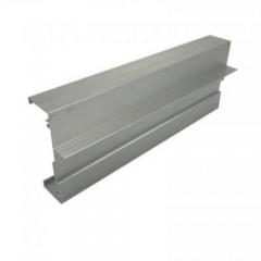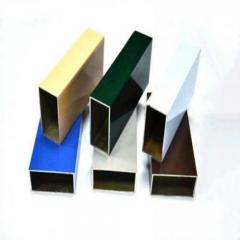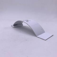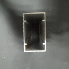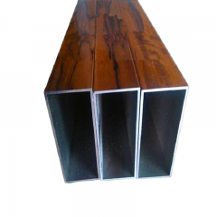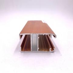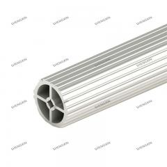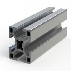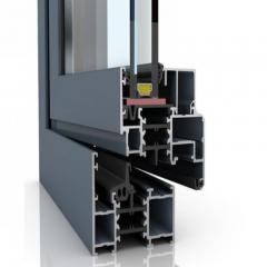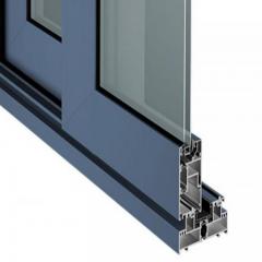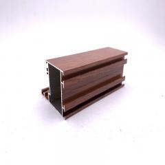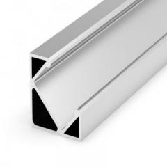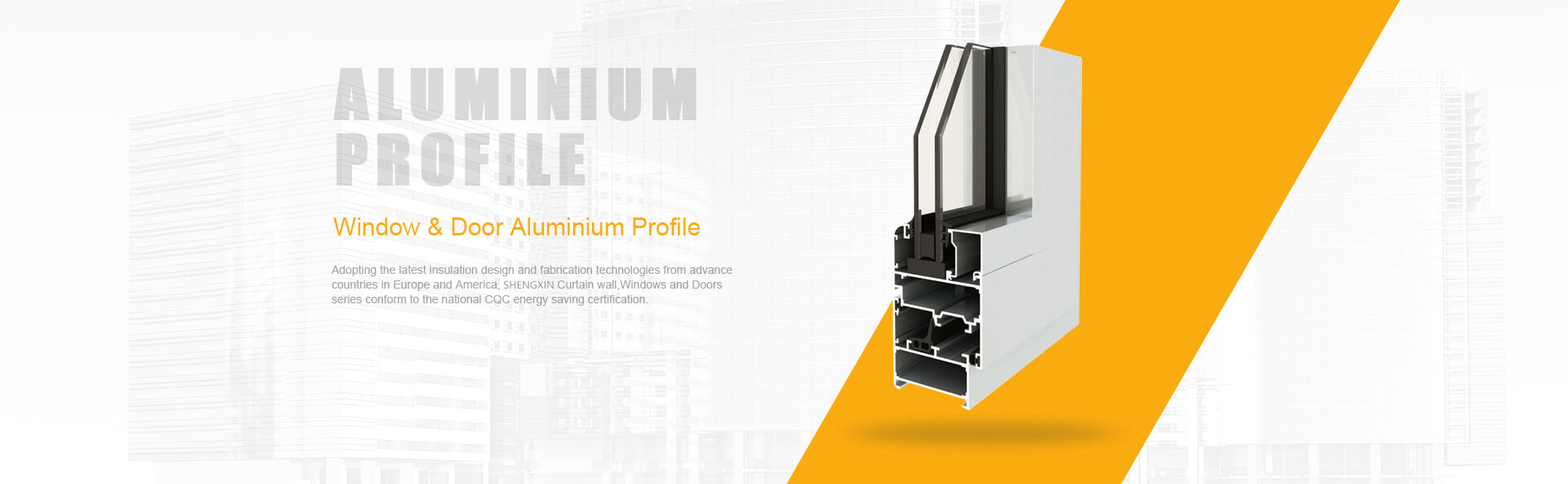
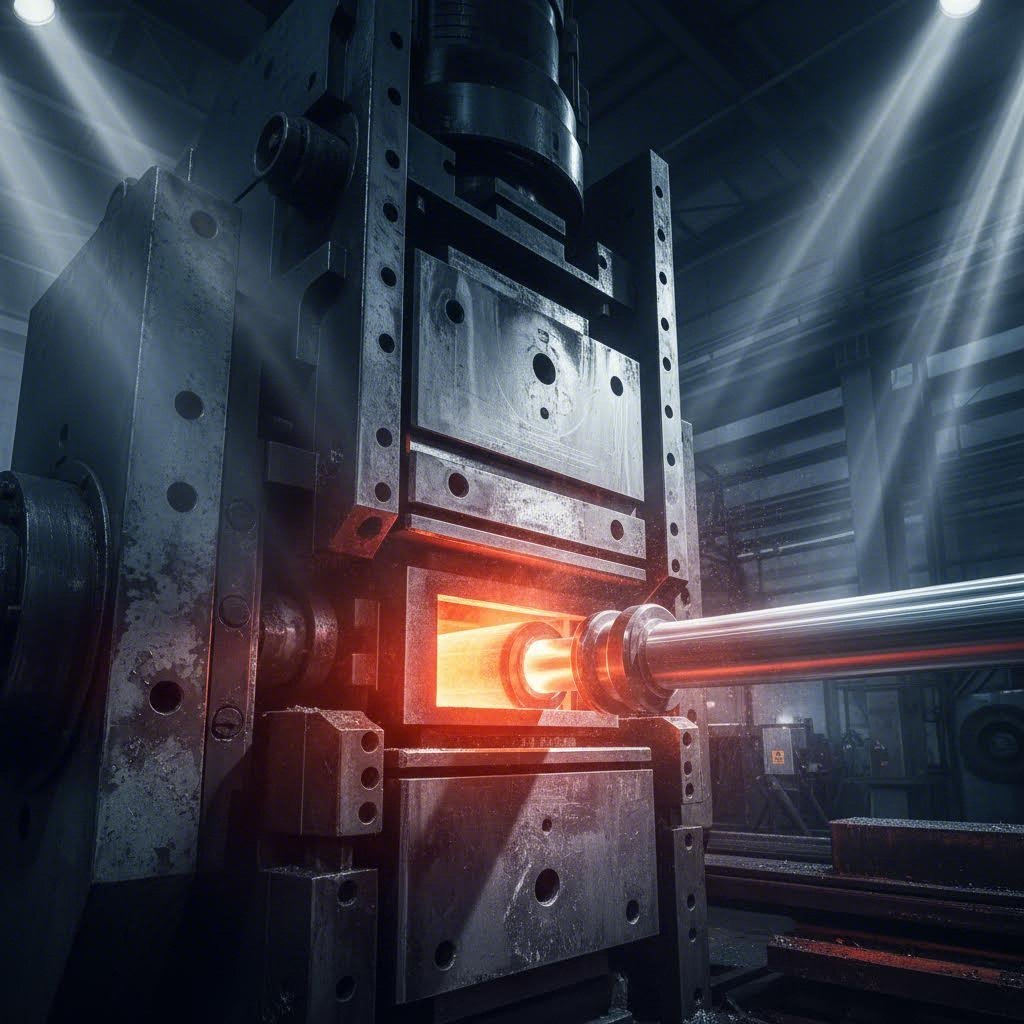
Ever wondered how manufacturers create those perfectly uniform aluminum channels, tubes, and complex profiles you see in everything from window frames to heat sinks? The answer lies in a fascinating process that transforms raw aluminum into precision-engineered shapes. This aluminum extrusion design guide begins with the essential knowledge every designer needs to leverage this versatile manufacturing method effectively.
Aluminum extrusion is a manufacturing process where heated aluminum alloy is forced through a shaped die opening to create continuous profiles with consistent cross-sections. The resulting shapes can be solid, hollow, or semi-hollow, ranging from simple geometric forms to highly complex custom designs.
Think of squeezing toothpaste from a tube. The continuous stream takes the shape of the round tip as it emerges. Aluminum extrusion works on the same principle, but with far greater precision and power. According to Hydro, powerful hydraulic presses exerting 100 to 15,000 tons of pressure can push aluminum into virtually any imaginable shape.
What sets this aluminum extrusion process apart is its ability to produce incredibly intricate cross-sectional geometries in a single operation. Unlike subtractive methods that cut away material, extrusion forms the desired shape directly, minimizing waste and maximizing material efficiency. The process also enhances aluminum's natural properties, creating profiles that are stronger and more resilient than the original billet material.
Understanding the aluminium extrusion meaning requires grasping what happens at each stage:
Simple shapes can emerge from the press at speeds up to 200 feet per minute, while complex profiles may move as slowly as one foot per minute. This flexibility allows the process to accommodate everything from basic angles to sophisticated multi-void hollow sections. It's worth noting that while pure aluminum extrusion with iron impurities must be carefully controlled, modern alloy formulations optimize trace elements for optimal extrudability and final properties.
When evaluating manufacturing options, you'll want to understand where extrusion excels compared to alternatives like CNC machining, die casting, or 3D printing:
Extrusion shines when your design features consistent cross-sections along its length. It delivers excellent material density, predictable quality, and competitive costs at scale. As noted by industry experts, extrusion offers stability and scalability that make it ideal for applications ranging from ESS cooling structures to large-format architectural profiles.
The aluminium extrusion definition ultimately comes down to this: it's a process optimized for creating long, straight profiles with complex cross-sections at high volumes. When your design fits these parameters, you'll find extrusion offers an unbeatable combination of design flexibility, structural integrity, and manufacturing economy that other processes simply cannot match.
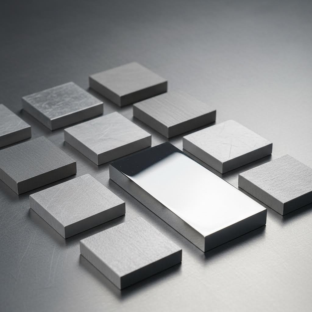
Now that you understand how aluminum extrusion works, here's the question that trips up many designers: which alloy should you specify? Your alloy selection directly influences everything from achievable wall thickness to surface finish quality. Get it wrong, and you'll face unnecessary manufacturing challenges or pay for properties you don't actually need. This section of our aluminum extrusion design guide walks you through practical decision-making criteria that most resources overlook.
The 6063 versus 6061 debate comes up in nearly every extrusion project. Both belong to the 6000 series aluminum family, using silicon and magnesium as primary alloying elements, but they serve distinctly different purposes.
According to Eagle Aluminum, 6063 aluminum is widely recognized for its excellent extrudability and superior surface finish, making it the preferred choice for architectural applications where visual appeal matters. Its smooth finish responds exceptionally well to anodizing, which is why you'll find it in window frames, door frames, and decorative trim work.
On the other hand, 6061 aluminum delivers significantly higher strength. When comparing the T6 tempers, 6061-T6 offers an ultimate tensile strength of at least 42,000 psi and yield strength of at least 35,000 psi. Compare this to 6063-T6, which provides an ultimate tensile strength of at least 28,000 psi and yield strength of 23,000 psi. That's roughly a 50% strength advantage for 6061.
So when do you choose one over the other? If your aluminium extrusion parts require structural load-bearing capability, 6061 is your answer. If surface aesthetics and finishing flexibility matter more than maximum strength, 6063 wins every time.
Beyond the 6063 versus 6061 comparison, several other alloys deserve consideration in your aluminum extrusion design process. The aluminium extruders council and broader aluminum council guidelines recognize multiple alloys optimized for specific applications:
| Alloy | Tensile Strength (T6) | Corrosion Resistance | Weldability | Surface Finish Quality | Typical Applications |
|---|---|---|---|---|---|
| 6063 | 28,000+ psi | Excellent | Very Good | Excellent | Architectural profiles, window frames, furniture, decorative trim |
| 6061 | 42,000+ psi | Very Good | Excellent | Good | Structural components, aerospace, marine applications, bicycle frames |
| 6005 | 38,000+ psi | Very Good | Good | Good | Ladders, rail profiles, structural tubing, heavy machinery |
| 6082 | 45,000+ psi | Excellent | Good | Moderate | Bridge engineering, shipbuilding, transportation structures |
Notice how 6005 aluminum offers a middle ground? As noted by Marine Aluminum, 6005 provides higher strength than 6063 with better extrusion characteristics than 6082. It's ideal when you need structural performance without the premium costs associated with aerospace-grade alloys.
For the most demanding structural applications, 6082 aluminum delivers the highest mechanical strength in the 6000 series. Its excellent corrosion resistance makes it particularly suited for shipbuilding, bridges, and transportation equipment where environmental exposure is a concern.
Your alloy choice creates a ripple effect throughout the aluminium extrusion manufacturing process. Here's what you need to understand:
Wall thickness minimums: Higher-strength alloys like 6061 and 6082 generally allow thinner walls while maintaining structural integrity. However, 6063's superior extrudability means it can achieve thinner sections more consistently during production. When specifying aluminum extrusion tolerances for thin-wall profiles, 6063 often provides better dimensional consistency.
Achievable tolerances: Alloys with excellent extrudability, particularly 6063, flow more uniformly through dies. This translates to tighter achievable tolerances and fewer dimensional variations across production runs. If your design demands precision, factor this into your alloy selection.
Surface treatment compatibility: Planning to anodize your profiles? 6063 accepts anodizing beautifully, producing consistent color and excellent finish quality. While 6061 can be anodized, the results may show more variation. For powder coating applications, all 6000-series alloys perform well, but proper surface preparation becomes more critical with higher-strength grades.
The key takeaway? Don't default to a single alloy for every project. Evaluate your specific requirements for strength, aesthetics, and manufacturability. A thoughtful alloy selection at the design stage prevents costly modifications and ensures your aluminium extrusion parts perform exactly as intended.
You've selected your alloy. Now comes the decision that makes or breaks your extrusion project: wall thickness. Specify walls too thin, and you'll face production nightmares, warped profiles, and rejected parts. Go too thick, and you're wasting material while increasing costs unnecessarily. This section of our aluminum extrusion design guide provides the specific dimensional guidelines that many resources mysteriously omit.
Here's what most design manuals won't tell you: minimum wall thickness isn't a single number. It varies based on your profile type, alloy selection, and even the circumscribing circle diameter of your design. According to the Aluminum Extruders Council, keeping your profile's circumscribing circle diameter (CCD) under 8 inches significantly reduces costs and opens up more supplier options.
The relationship between CCD and wall thickness matters because larger profiles require proportionally thicker walls to maintain structural integrity during extrusion. Think of it this way: a 2-inch wide channel can hold its shape with thinner walls than a 10-inch wide panel, simply because the unsupported spans are shorter.
| Application Type | Minimum Wall Thickness | Optimal Range | Consequences of Going Too Thin |
|---|---|---|---|
| Architectural (6063) | 0.040" (1.0mm) | 0.050" - 0.080" (1.25-2.0mm) | Surface waviness, inconsistent anodizing, visible die lines |
| Structural (6061/6005) | 0.062" (1.6mm) | 0.080" - 0.125" (2.0-3.2mm) | Distortion during quenching, reduced load capacity, dimensional instability |
| Heat Sink | 0.030" (0.76mm) for fins | 0.040" - 0.060" (1.0-1.5mm) | Fin breakage during handling, uneven fin height, thermal performance loss |
| Decorative/Trim | 0.035" (0.9mm) | 0.045" - 0.065" (1.1-1.6mm) | Denting during shipping, poor surface quality, visible deflection |
| Hollow Profiles | 0.050" (1.27mm) | 0.062" - 0.125" (1.6-3.2mm) | Wall collapse during extrusion, eccentricity issues, weld line weakness |
These aluminum extrusion dimensions represent industry-standard minimums for most extruders. However, specialized micro-extrusion facilities can achieve thinner walls for certain applications. The key point? Always verify capabilities with your specific supplier before finalizing specifications for extruded aluminum sizes outside standard ranges.
Sounds complex? Here's the practical reality: your wall thickness specification creates a direct trade-off between part performance and production efficiency. Understanding this relationship helps you make smarter design decisions.
Die life considerations: Thinner walls require dies with correspondingly thinner sections. These delicate die features wear faster and are more prone to cracking. A die producing 0.040" walls might last for 50 tons of aluminum before requiring rework, while one producing 0.080" walls could process 150 tons or more. This directly affects your per-piece tooling cost allocation.
Extrusion speed impact: According to Taber Extrusions, complex profiles with thin sections extrude more slowly than simple, thick-walled shapes. Slower speeds mean higher labor costs per foot of extrusion. When you specify aluminum extrusion sizes with unnecessarily thin walls, you're paying for that decision in reduced throughput.
Quality implications: Thin-walled sections are more susceptible to:
The aluminum extrusion design guidelines from industry experts consistently recommend this approach: specify the minimum wall thickness that meets your structural and aesthetic requirements, then add 10-15% as a manufacturing safety margin. This buffer accounts for normal production variations while keeping costs reasonable.
Let's address the common mistake directly: designers often specify walls thinner than necessary, assuming lighter weight automatically means better design. Here's why that logic fails:
The tolerance trap: According to industry tolerance standards, wall thickness tolerances are expressed as percentages or fixed values depending on the specification. For walls under 0.062", standard tolerances of ±0.006" represent a significant percentage of the total dimension. This means a 0.040" specified wall could legitimately measure anywhere from 0.034" to 0.046" and still be within specification. If your design assumes exactly 0.040", you may have functional problems with compliant parts.
Hollow profile challenges: Hollow sections face additional constraints. The die must create an internal mandrel supported by bridges, and metal must flow around these bridges before rejoining. The standard tolerance tables show that wall thickness tolerances for hollow profiles are typically agreed upon between purchaser and vendor, especially when one wall is three times thicker than the opposite wall. Asymmetric wall distributions create uneven flow and potential quality issues.
Varying wall thickness within profiles: Sometimes your design legitimately requires different wall thicknesses in different areas. When transitioning between thick and thin sections, follow these aluminum extrusion design guidelines:
The Aluminum Extruders Council emphasizes that balanced walls and symmetrical details represent fundamental good design practices. When wall thickness varies dramatically across a profile, metal flows at different speeds through different die sections. This creates internal stresses that manifest as twist, bow, or camber in your finished parts.
Die flow balance: Imagine pushing modeling clay through a stencil with both thick and thin openings. The clay exits faster through the larger openings, creating uneven extrusion. The same physics applies to aluminum. Your extruder can partially compensate through die design, but severely unbalanced profiles will always be more difficult and expensive to produce.
The bottom line? Your wall thickness specifications directly influence die longevity, production speed, and dimensional consistency. Resist the temptation to minimize every dimension. Instead, optimize for the complete picture: structural requirements, surface quality expectations, tolerance needs, and manufacturing economics. This balanced approach leads to profiles that perform reliably while remaining cost-effective to produce at scale.
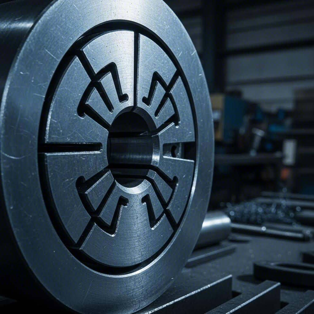
Your wall thickness is specified. Your alloy is selected. But here's what separates experienced designers from novices: understanding how your design decisions translate into the aluminum extrusion die that ultimately determines part quality. Every profile feature you specify must be carved into hardened H13 steel, then withstand up to 15,000 tons of pressure as heated aluminum forces its way through. This section reveals the die design considerations that directly impact your final profile's quality, consistency, and cost.
Think of the extrusion die as the DNA of your profile. According to Gabrian International, an extrusion die is a thick steel disk with an opening that matches your specified cross-sectional profile. The aluminum billet passes through this opening, emerging as your designed shape. Simple concept, complex execution.
The relationship between profile complexity and die cost follows a clear pattern. Your extrusion shapes fall into three categories, each requiring different aluminium extrusion tooling approaches:
Solid dies produce shapes without enclosed voids, such as angles, channels, and solid bars. These represent the simplest and most economical die configuration. A flat-face die has openings matching your profile exactly, with material flowing directly through. For continuous production runs, pocket dies or feeder dies add complexity but improve weld quality between successive billets.
Hollow dies create profiles with one or more fully enclosed voids, from simple rectangular tubes to complex multi-void t-slots. These require porthole dies consisting of two interlocking pieces: the mandrel forms internal features while the cap creates external geometry. The mandrel includes multiple portholes separated by supporting webs, through which aluminum flows before rejoining to form the hollow section.
Semi-hollow dies handle profiles with partially enclosed voids. Imagine a deep, narrow channel where the opening is significantly smaller than the void area. The "tongue ratio" formula (Area/Gap²) determines classification. Higher tongue ratios mean greater extrusion difficulty and increased die stress in the tongue area.
Certain design features dramatically increase die complexity, manufacturing difficulty, and cost. When you're specifying your extrusion die design, watch for these challenges:
The minimum feature size you can specify depends directly on profile complexity. For solid profiles, internal radii of 0.020" to 0.030" are typically achievable. Hollow and semi-hollow profiles require larger radii, typically 0.040" minimum, to maintain die strength in the mandrel's tongue areas.
Corner radii requirements deserve special attention. Sharp corners are the enemy of die longevity. Internal corners should have radii of at least 0.020" for solid sections and 0.040" for hollow sections. External corners benefit from 0.015" minimum radii. These seemingly small dimensions significantly impact both die life and your profile's structural integrity at stress concentration points.
Proper extrusion die design isn't just about creating your shape once. It's about creating it consistently across thousands of feet of extrusion while maximizing die life. Here's how your design decisions influence long-term production quality:
Smooth all transitions: As recommended by industry design guides, transitions between thick and thin sections should be streamlined with generous radii. Abrupt changes cause turbulent metal flow, leading to surface defects and die wear at transition points.
Keep wall thickness uniform: Beyond structural considerations, uniform walls ensure balanced metal flow through the die. When aluminum exits at different speeds from different die sections, the profile twists or bows. Your die maker can partially compensate, but inherently balanced designs always produce better results.
Consider die support tooling: Every die for aluminium extrusion requires backers and bolsters to withstand press pressure. The backer sits directly behind the die with an opening slightly wider than the profile, preventing die deformation. The bolster provides additional support behind the backer. Complex profiles may need sub-bolsters for maximum rigidity.
Tongue-and-groove limitations: Planning interlocking features? The tongue-and-groove geometry must account for both die manufacturability and thermal expansion during extrusion. Allow minimum 0.015" clearance beyond your functional requirement, and avoid deep, narrow grooves that create high tongue ratios.
The investment in proper aluminium extrusion tooling pays dividends throughout production. A well-designed die might process 150+ tons of aluminum before requiring rework, while a poorly conceived design may fail after just 20-30 tons. Since die costs represent a significant upfront investment, maximizing die life directly reduces your per-piece costs.
The key insight? Engage with your die maker and extruder early in the design process. As Gabrian notes, collaboration between designer, tool shop, and extruder is essential for manufacturability. Minor design modifications that seem insignificant on paper can dramatically improve die life, dimensional consistency, and surface quality in production. This collaborative approach prevents costly redesigns and ensures your extrusion shapes perform exactly as intended from the first production run.
Your die is designed and your walls are specified. But here's where many projects go sideways: tolerance specifications. Request unnecessarily tight tolerances, and you'll pay premium prices for precision you don't actually need. Specify tolerances too loosely, and your parts won't fit their intended assemblies. This section of our aluminum extrusion design guide demystifies tolerance standards with practical guidance that goes beyond the vague references you'll find elsewhere.
Two primary standards govern aluminium extrusion design guidelines for dimensional tolerances in most applications. According to Shapes by Hydro, EN 12020-2 applies to architectural alloys like 6060 and 6063, while EN 755-9 covers heavier structural alloys including 6005, 6082, and the 7000 series. As a practical rule of thumb, EN 12020-2 tolerance values are approximately 0.7 to 0.8 times the values specified in EN 755-9.
In North America, the Aluminum Extruders Council references tolerance tables published in Aluminum Standards and Data by The Aluminum Association. Tables 11.5 through 11.14 and Tables 12.2 through 12.14 cover dimensional tolerances for various profile types and characteristics.
What does this mean for your project? Tolerance classes typically break down into three tiers:
| Tolerance Class | Wall Thickness | Angles | Straightness (per ft) | Twist (per ft) | Typical Applications |
|---|---|---|---|---|---|
| Standard | ±0.008" to ±0.012" | ±1° | 0.012" per foot | 1° per foot | General architectural, decorative trim, non-critical assemblies |
| Precision | ±0.004" to ±0.006" | ±0.5° | 0.006" per foot | 0.5° per foot | Window frames, mechanical assemblies, snap-fit components |
| High-Precision | ±0.002" to ±0.004" | ±0.25° | 0.004" per foot | 0.25° per foot | Heat sinks, precision machinery, optical equipment mounts |
Beyond these primary dimensions, the aluminium extrusion process introduces six distinct tolerance categories that affect part quality. As noted by Hugh Aluminum, these include angular tolerance, flatness, straightness, twist, shape accuracy, and dimensional accuracy. Each category requires independent evaluation based on your application's functional requirements.
Sounds straightforward? Here's where it gets nuanced. Achievable tolerances depend heavily on your profile's circumscribing circle diameter (CCD). Larger profiles inherently exhibit greater dimensional variation simply due to the physics of metal flow and cooling.
According to Shapes by Hydro, certain measurements can often achieve smaller tolerances depending on the shape and complexity of the extrusion. The key is understanding where tight tolerances genuinely matter versus where they add cost without functional benefit.
Consider tighter tolerances when:
Standard tolerances typically suffice when:
The relationship between tolerance requirements and aluminum extrusion tooling costs is direct. Tighter tolerances demand more precise die manufacturing, more frequent die corrections, and slower extrusion speeds to maintain dimensional consistency. Each factor adds cost that flows through to your per-piece pricing.
Here's practical guidance that can save significant project costs: specify tolerances based on functional requirements, not assumptions about quality. Many designers default to requesting the tightest tolerances available, assuming this ensures better parts. In reality, it ensures higher prices without corresponding value.
The Aluminum Extruders Council emphasizes that tolerance requirements are often an important discussion topic between designer and extruder. Many extruders can achieve tighter tolerances than standard tables indicate, but this capability comes at a cost. The key is matching capability to actual need.
How precision requirements affect production:
A strategic approach involves specifying mixed tolerances: tight precision only on dimensions critical to function, with standard tolerances elsewhere. For example, a window frame profile might require precision angular tolerances for seal surfaces while accepting standard tolerances on decorative features. This targeted specification optimizes cost without compromising performance where it matters.
The bottom line for your aluminium extrusion design guidelines? Start by identifying which dimensions are truly critical to your application's function. Discuss these requirements with your extruder early in the design process. Often, minor design modifications can dramatically improve achievable tolerances without the cost premium of blanket precision specifications. This collaborative approach ensures you get the precision you need at a price that makes sense for your production volumes.
You've established your tolerances and die requirements. Now comes a decision that significantly impacts both project budget and timeline: should you select from standard aluminum extrusion profiles or invest in custom die development? This choice shapes everything from initial costs to long-term production economics. Understanding the full spectrum of available options helps you make the smartest decision for your specific application.
Before jumping to custom designs, explore what's already available. According to Taber Extrusions, manufacturers maintain extensive inventories of standard aluminum extrusions shapes covering most common applications. These stock profiles eliminate die development costs and dramatically reduce lead times.
Here's how the extruded aluminum shapes catalog typically organizes standard options:
The cost advantage of standard profiles is substantial. As noted by industry research, standard aluminum extrusions are typically 30% to 50% less expensive than custom alternatives. This difference stems from eliminated die costs and the economies of mass production. When reviewing a standard aluminum extrusion profiles pdf or catalog, you're looking at shapes optimized for both manufacturability and cost-effectiveness.
Lead time differences are equally significant. Standard profiles typically ship within 7 to 14 days since suppliers maintain ready inventory. Custom profiles require 15 to 30 days minimum, accounting for die design, fabrication, and initial production runs.
Despite the cost advantages of standard shapes, custom aluminum extrusion profiles often make more economic sense for specific applications. The key is understanding when the higher upfront investment pays off.
According to Gabrian International, many product designers encounter situations requiring non-standard shapes, specialized finishes, or uncommon alloys. When standard profiles won't meet your requirements, custom extrusions become the practical choice.
Custom profiles deliver superior value when:
The tooling investment varies significantly by complexity. Simple solid profile dies start around $1,250, while hollow dies run approximately $1,950. Complex or multi-hollow dies can reach $5,000 or more. For medium complexity profiles, expect $1,500 to $3,000 in die development costs.
Here's the economic reality: if your project requires 500 meters of extrusion, die costs add substantially to per-unit pricing. At 10,000 meters, those same die costs become negligible per piece. As production volumes increase, custom alu extrusion profiles increasingly outcompete standard alternatives modified through secondary operations.
Large aluminum extrusions present unique design considerations that deserve special attention. As circumscribing circle diameters increase, metal flow characteristics change, tolerances become more challenging, and fewer suppliers can accommodate your requirements.
Part consolidation strategy: One of the most powerful applications of custom extrusions is consolidating multiple parts into a single profile. Imagine replacing an assembly of three aluminum angles, fasteners, and a backing plate with one integrated extrusion. You eliminate:
The savings extend beyond direct material costs. Reduced assembly time, simplified quality control, and improved structural integrity often justify custom die investment even at moderate volumes.
Designing for manufacturability: When creating aluminum extrusions profiles for complex applications, apply these principles from our earlier discussions:
Joining methods also expand your design possibilities. According to extrusion design experts, including joints in your design can make manufacturing easier and cheaper when a single profile would be too large, asymmetric, or complex. Specialized hinge joints even allow limited rotation at connection points.
The decision between standard and custom ultimately depends on your specific balance of volume, complexity, and timeline requirements. For projects where standard catalog shapes meet functional needs, the cost and speed advantages are compelling. When your application demands optimized performance, reduced assembly complexity, or specific geometric features, custom aluminum extrusion profiles deliver value that justifies the investment. Understanding both options ensures you choose the path that best serves your project's complete requirements.
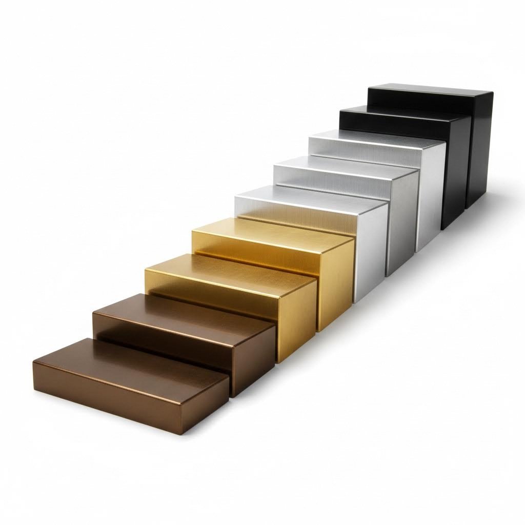
Your profile shape is finalized and tolerances are specified. But here's a decision that affects both the visual appeal and long-term performance of your aluminum extruded profiles: surface treatment selection. The finish you choose doesn't just determine color and appearance. It influences corrosion resistance, durability, maintenance requirements, and even your base alloy selection. This section of our aluminum extrusion design guide walks you through the complete spectrum of finishing options and their design implications.
| Surface Treatment | Durability Rating | Color Options | Cost Level | Best Applications |
|---|---|---|---|---|
| Mill Finish | Low-Moderate | Natural aluminum only | Lowest | Industrial equipment, hidden components, secondary machining parts |
| Anodizing | High | Limited palette (bronze, black, gold, silver, architectural colors) | Moderate | Architectural facades, consumer electronics, decorative trim |
| Powder Coating | High | Unlimited colors, textures, metallics | Moderate | Outdoor furniture, appliances, industrial enclosures |
| PVDF Coating | Very High | Wide palette with excellent retention | High | Curtain walls, storefronts, architectural fenestration |
| Micro-Arc Oxidation | Very High | Limited (gray, black, natural) | Highest | High-wear components, aerospace, marine applications |
When you need both durability and a refined metallic appearance, anodizing stands out as the go-to treatment for aluminum profile extrusion. According to BRT Extrusions, anodizing is an electrochemical process that creates a durable, corrosion-resistant oxide layer on the aluminum surface. This layer becomes an integral part of the metal rather than sitting on top like paint.
What makes anodizing particularly valuable for your alu extrusion profile? The process significantly enhances natural corrosion resistance while offering versatile aesthetic options. The anodic oxide layer acts as a barrier against moisture, chemicals, and UV radiation, making anodized profiles ideal for outdoor and high-moisture environments.
Color capabilities and limitations: Anodizing allows for a wide range of color options through dyeing the oxide layer. However, you'll notice the color palette differs from paint. Traditional anodized finishes include:
Here's an important design consideration: anodizing works best with 6063 alloy. As noted in HY Aluminum's guide on surface treatments, the thickness and color of anodized layers can be adjusted to meet specific requirements. However, 6061 and higher-strength alloys may show color variation due to their different chemical compositions. If consistent anodized appearance is critical, specify 6063 from the start.
Dimensional implications: Anodizing adds thickness to your profile. Standard architectural anodizing (Class I) builds approximately 0.0007" per surface, while Class II is thinner at 0.0004". Account for this buildup when specifying tolerances for mating surfaces or tight-clearance assemblies.
Need virtually unlimited color options? Powder coating opens design possibilities that anodizing simply cannot match. According to industry experts, powder coating is a dry finishing process that electrostatically applies powder material to the aluminum surface, then cures it under heat to form a smooth, hard finish.
For aluminum door extrusion and window frame applications, powder coating delivers several compelling advantages:
Unlike anodizing, powder coating works well across all common extrusion alloys. This flexibility means you can specify 6061 for structural strength while still achieving the exact color your design requires. For aluminium extrusions profiles destined for architectural applications, powder coating provides the design freedom architects demand.
Application considerations: Powder coating thickness typically ranges from 0.002" to 0.004", significantly more than anodizing. This additional buildup requires attention when designing snap-fit features, sliding interfaces, or precision assemblies. The coating also performs better on profiles with generous radii, as sharp edges may show reduced coverage.
Design complexity also influences finish selection. As BRT Extrusions notes, anodizing is often better suited for intricate shapes and fine details, while powder coating provides smooth, uniform coverage on complex profiles. Consider your profile geometry when making this decision.
When standard anodizing or powder coating doesn't meet your performance requirements, specialty finishes fill critical application gaps.
PVDF coatings: According to Sherwin-Williams, 70 percent polyvinylidene difluoride (PVDF) coatings have become one of the most respected extrusion coatings for architectural applications. Originally introduced in 1965, these coatings deliver exceptional color retention and weathering resistance that no other coating system can match.
What makes PVDF the premium choice for architectural aluminum profile extrusion?
For curtain walls, window framing, storefronts, and entrance systems, PVDF coatings justify their higher cost through exceptional longevity. Major architectural projects specify PVDF precisely because building owners can trust the finish to maintain appearance for 20+ years with minimal maintenance.
Electrophoresis coating: As described by HY Aluminum, electrophoresis deposits coating material through electric field action, creating smooth, uniform films with excellent corrosion resistance. This process suits complex-shaped profiles where other methods struggle to achieve consistent coverage.
Micro-arc oxidation: For the most demanding wear and corrosion applications, micro-arc oxidation creates ceramic-like surfaces with exceptional hardness. While color options are limited and costs are highest, this treatment provides unmatched performance for aerospace, marine, and heavy industrial applications.
Pre-treatment importance: Regardless of your final finish selection, surface preparation requirements should inform your initial design decisions. Phosphating, for example, improves adhesion for subsequent powder coating or painting. Specify your finish early so your extruder can ensure proper cleaning, etching, and pre-treatment protocols throughout production.
The key takeaway? Your surface treatment decision cascades through multiple design considerations: alloy selection, dimensional tolerances, profile geometry, and production specifications. By understanding how each finish option performs and what it requires, you position your aluminum extruded profiles for both aesthetic success and long-term durability in their intended environment.
Your surface treatment is selected and your profile specifications look complete on paper. But here's the reality: even experienced designers make costly mistakes that derail extrusion projects. According to MMG Extrusions, aluminum extrusion manufacturers consistently encounter the same design issues when receiving new profile specifications. Understanding these pitfalls before finalizing your drawings saves both time and significant project costs.
What separates successful custom aluminum extrusion profiles from problematic ones? Often, it comes down to understanding why certain design approaches fail during manufacturing. Let's examine the five most common mistakes and their solutions, with the reasoning behind each correction.
The mistake: Designers often request the tightest tolerances available, assuming this ensures higher quality parts.
The manufacturing consequence: Excessively tight tolerances increase die costs by 20-40%, slow production speeds, require more frequent quality checks, and drive up rejection rates. Your per-piece costs climb substantially without corresponding functional benefit.
The correct approach: Specify tolerances based on actual functional requirements, not assumptions about quality. As noted by BWC Profiles, productivity and price are both affected when tolerances are tighter than necessary. Identify which dimensions are truly critical to your application, then specify precision only where it matters. Standard tolerances work perfectly for most non-mating surfaces.
The mistake: Designing profiles with perfectly vertical walls and ignoring how aluminum flows through the die.
The manufacturing consequence: Without appropriate consideration for die release and metal flow, profiles may stick during extrusion, show surface defects, or exhibit dimensional instability. Dies wear faster when metal doesn't flow smoothly through the opening.
The correct approach: Design with manufacturing in mind from the start. According to Gabrian International, slight tapers facilitate easier material flow and part release. While extrusion differs from die casting, the principle applies: generous radii at all corners and transitions ensure aluminum flows smoothly through the die, reducing turbulence and surface defects.
The mistake: Designing thin walls or fins without adequate support, or specifying extreme wall thickness variations within the same profile.
The manufacturing consequence: As highlighted by industry experts, thin walls or substantial variations in wall thickness create problems with metal flow during extrusion. Unsupported thin sections deflect, break during handling, or exhibit severe distortion after cooling.
The correct approach: Maintain a maximum thickness ratio of 3:1 between adjacent walls. Add support ribs or bridges to thin sections requiring structural integrity. When building with aluminum extrusion, remember that uniform wall thickness makes profiles easier to extrude and more dimensionally stable. If your design requires varying thicknesses, use gradual transitions rather than abrupt steps.
The mistake: Designing profiles in isolation without considering how they'll mate with other components during aluminum extrusion assembly.
The manufacturing consequence: Profiles that look perfect individually may not fit together properly. Tolerance stack-up across multiple mating surfaces creates gaps, interferences, or alignment problems that only become apparent during final assembly.
The correct approach: According to BWC Profiles, you need to think through final assembly needs during your design phase to ensure your design is extrudable and will fit with mating components. Design interlocking features with appropriate clearances for thermal expansion. Include registration features that guarantee proper alignment. Consider how fasteners, gaskets, or adhesives will interact with your profile geometry.
The mistake: Creating asymmetric profiles or unbalanced cross-sections without understanding their impact on extrusion quality.
The manufacturing consequence: When metal flows at different speeds through various die sections, profiles twist, bow, or develop internal stresses. As emphasized by extrusion specialists, the more asymmetrical or unbalanced a shape, the less likely it is to remain straight or hold its shape accurately.
The correct approach: Make profiles symmetrical where possible. When asymmetry is unavoidable, work with your extruder to balance die flow through bearing adjustments or other die modifications. Position heavier sections centrally when practical. Understand that simple, symmetrical designs with similar wall thicknesses are more cost-efficient, extend die life, and improve production yield.
Symmetry deserves special attention because it affects nearly every aspect of extrusion quality. When you design an asymmetric profile, you're essentially asking the die to create unequal resistance to metal flow. The aluminum naturally accelerates through larger openings while slowing through constricted areas.
Imagine the consequences: one side of your profile exits the die faster than the other. The result? Curved extrusions, twisted shapes, and profiles that won't meet straightness specifications. Your extruder can partially compensate through die design, but inherently balanced profiles always produce better results.
If your application genuinely requires asymmetry, consult with your die maker early. Sometimes minor design modifications, such as adding balancing features or adjusting local wall thicknesses, dramatically improve extrudability without compromising function.
According to industry guidance, sharp corners should be avoided to assist aluminum flow through the die. But why do sharp corners create such problems?
The physics are straightforward: metal flowing around a sharp corner creates turbulence, much like water rushing around a rock in a stream. This turbulence leads to:
The solution? Corners should be radiused to assist extrusion flow. Blend radii should ease the flow from one mass area to the next, preventing surface imperfections. For internal corners, specify minimum radii of 0.020" for solid profiles and 0.040" for hollow sections. External corners benefit from at least 0.015" radii. These small dimensions yield significant improvements in die life, surface quality, and structural integrity.
Here's a mistake that impacts aluminum extrusion cost more than most designers realize: failing to plan for secondary operations during initial design.
Secondary operations include CNC machining, drilling, tapping, bending, and finishing processes performed after extrusion. When you design without considering these steps, you may create profiles that are difficult or expensive to process further.
Common secondary operation oversights:
The correct approach involves designing for the complete manufacturing sequence. If your profile requires holes, consider whether the extrusion can include pilot features that simplify drilling operations. If bending is required, ensure wall thicknesses and radii support forming without cracking. If machining is necessary, include adequate material for fixturing and ensure cutting tools can access all features.
According to MMG Extrusions, lack of proper information and product requirements ranks among the most common design issues manufacturers encounter. Communicate your complete requirements, including secondary operations, finish specifications, and assembly needs, when submitting profile designs. This comprehensive approach prevents costly surprises and ensures your custom aluminum extrusion profiles meet all functional requirements from the first production run.
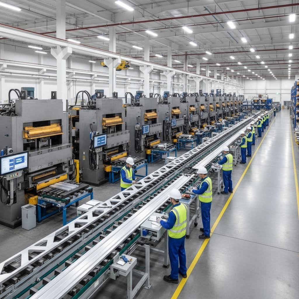
You've refined your design, specified tolerances, and selected surface treatments. Now comes the phase that transforms your aluminum extrusion catalog of ideas into physical products: partnering with a supplier who can execute your vision. This transition from design to production involves critical decisions about timelines, costs, and communication protocols that directly impact project success. Understanding what suppliers need from you, and what you should expect from them, prevents costly miscommunications and ensures smooth production runs.
Wondering what the journey from initial concept to finished aluminum profile extrusions actually looks like? The typical project timeline follows a predictable sequence, though duration varies based on complexity and supplier capacity.
According to industry sources, three primary factors influence production lead time: tooling lead time, extrusion lead time, and fabrication lead time. Here's how each phase typically unfolds:
Phase 1: Design review and quotation (1-2 weeks)
Your supplier evaluates your drawings for manufacturability, identifies potential issues, and provides pricing. This initial review often reveals optimization opportunities that reduce costs without compromising function. Experienced aluminum extrusion builders will suggest modifications to improve die life, reduce material usage, or simplify secondary operations.
Phase 2: Die development (2-4 weeks)
Once you approve the quotation and design, die manufacturing begins. Simple solid profiles require less time than complex hollow sections. As noted by PSI Industries, a detailed cross-sectional drawing of the profile shape is made, then cut into a disk of hardened H13 tool steel to create the die.
Phase 3: Sampling and approval (1-2 weeks)
Initial extrusion runs produce samples for your evaluation. You'll verify dimensional accuracy, surface quality, and overall conformance to specifications. According to KMC Aluminium, when a new die is first run, additional systems ensure operational conditions produce the required quality. The die may require minor adjustments before achieving optimal results.
Phase 4: Mass production (variable)
With approved samples, full production begins. Duration depends on order quantity, profile complexity, and secondary operations required. Straightforward orders may complete in days, while large aluminium extrusions with extensive fabrication needs extend to weeks.
Phase 5: Finishing and fabrication (1-3 weeks additional)
If your project requires surface treatments, machining, or assembly, add this time to your planning. As reference materials indicate, fabrication lead times for coating, deburring, anodizing, cutting to length, and drilling can add days or even weeks depending on complexity.
Die investment represents a significant upfront cost that deserves careful consideration. Understanding what drives die pricing helps you make informed decisions about custom extruded aluminum profiles versus standard alternatives.
Die cost factors:
According to industry experts, die costs vary based on profile type and complexity:
The total tooling package extends beyond the die itself. A typical extrusion operation involves the die assembly contained within a die ring, placed in front of a backer with a sub-bolster, all contained within a tool carrier. Complex profiles may require additional supporting components, increasing total tooling investment.
Minimum order quantities explained:
Why do suppliers require minimum orders? The reasons are both economic and technical. According to KMC Aluminium, several factors establish MOQ requirements:
The relationship between press size and MOQ is straightforward: larger presses handling larger profiles require higher minimum quantities to justify production runs. When evaluating apex aluminium extrusions suppliers or any potential partner, ask specifically about MOQ requirements for your profile size and complexity.
What information does your supplier need to provide accurate quotes and successful production? Comprehensive documentation prevents misunderstandings and enables realistic pricing. When submitting your custom extruded aluminum profiles for quotation, include:
According to industry guidance, when the product designer, die designer, extruder, and buyer recognize each other's requirements and work together, the best combination of product performance, quality, and cost is achieved.
Evaluating potential partners:
When selecting an extrusion supplier for your aluminum extrusion catalog of projects, consider capabilities that span the complete production sequence. Full-service partners like Shengxin Aluminium demonstrate the value of integrated capabilities. With over 30 years of industry experience and 35 advanced extrusion presses ranging from 600T to 5500T capacity, they provide end-to-end support from die development through mass production.
Look for partners offering comprehensive secondary processing. State-of-the-art CNC machining centers capable of precise cutting, drilling, and bending eliminate the need to coordinate multiple vendors. Similarly, in-house surface treatment capabilities including anodizing in custom colors, powder coating, PVDF, and micro-arc oxidation streamline production while ensuring quality control throughout the process.
Cost optimization strategies:
Your design choices directly affect per-piece pricing beyond obvious material costs. Consider these factors when finalizing specifications:
As reference materials emphasize, aluminum extrusion tooling costs are generally much lower than alternatives such as die-casting, roll forming, or stamping. This cost advantage makes extrusion particularly attractive for medium to high-volume production of complex profiles.
The key to supplier success? Early engagement and clear communication. Share your complete requirements, including application context, assembly needs, and performance expectations. Suppliers with technical depth can identify optimization opportunities that reduce costs while improving manufacturability. This collaborative approach transforms the supplier relationship from transactional ordering into genuine partnership that benefits your projects from first sample through ongoing production runs.
You've absorbed the principles, studied the specifications, and learned from common mistakes. Now it's time to transform this knowledge into a systematic approach you can apply to every extrusion profile you design. This final section of our aluminum extrusion design guide consolidates everything into actionable frameworks that streamline your design process and improve outcomes from the very first project.
Successful extrusion design isn't about perfecting individual specifications in isolation. It's about understanding how alloy selection, wall thickness, tolerances, die complexity, and surface treatments interact as an integrated system where each decision influences the others.
Before sketching your first line or opening CAD software, work through this comprehensive checklist. According to Profile Precision Extrusions, starting with a basic sketch or detailed CAD file that specifies your ideal dimensions and tolerances sets the foundation for successful collaboration with your extruder.
How do you navigate the trade-offs inherent in every design decision? The answer lies in understanding that different applications legitimately lead to different design choices. Your aluminium design manual approach should follow a decision-tree logic:
When aesthetics drive requirements: Specify 6063 alloy for superior surface finish. Accept slightly lower strength in exchange for excellent anodizing response. Prioritize surface quality over minimum wall thickness. Invest in PVDF or high-quality powder coating for long-term appearance retention.
When structural performance is paramount: Select 6061, 6005, or 6082 based on required strength levels. Optimize profile aluminum extrusion geometry to maximize section modulus and moment of inertia. Specify tighter tolerances on load-bearing surfaces. Accept that surface treatment options may be somewhat limited.
When cost optimization takes priority: Evaluate standard catalog shapes before committing to custom dies. Design for symmetry and uniform walls to maximize production speed and die life. Specify standard tolerances wherever possible. Consider part consolidation to eliminate assembly costs even if die investment increases.
When production volume is high: Invest in optimized custom dies that reduce per-piece costs over extended runs. Specify alloys and geometries that maximize extrusion speed. Design for automated secondary operations. According to design for manufacturability principles, early-stage decisions significantly impact overall success, cost, and timeline.
The aluminum section you ultimately specify should reflect conscious choices within this framework rather than default assumptions. Every project presents unique constraints, and the optimal design emerges from deliberately balancing competing requirements rather than maximizing any single parameter.
Ready to move from planning to production? Here's your roadmap for turning designs into finished parts:
Step 1: Finalize your design documentation. Complete your drawings with all dimensional specifications, tolerance callouts, and material requirements. Include notes on surface treatment expectations and secondary operation needs. The more complete your documentation, the more accurate your quotations.
Step 2: Engage suppliers early. Don't wait until designs are "perfect" to seek input. Experienced extruders identify manufacturability issues and optimization opportunities that improve outcomes. As industry experts note, free design consultations help bring new designs to life while avoiding costly revisions later.
Step 3: Evaluate partner capabilities. Look for suppliers offering comprehensive services from die development through finishing. Partners with integrated CNC machining, multiple surface treatment options, and technical support streamline production while ensuring consistent quality. For designers seeking this complete capability set, Shengxin Aluminium exemplifies what to look for: over 30 years of experience, 35 extrusion presses spanning 600T to 5500T capacity, state-of-the-art CNC machining centers, and comprehensive surface treatments including anodizing in custom colors, powder coating, PVDF, and micro-arc oxidation.
Step 4: Review samples thoroughly. When initial extrusions arrive, verify every specification against your requirements. Check dimensional accuracy, surface quality, and material properties. This approval gate prevents production issues before volumes scale.
Step 5: Establish ongoing communication. The best supplier relationships evolve into true partnerships. Share application feedback, discuss volume forecasts, and collaborate on continuous improvement. Whether you need custom 6063 aluminum tubes, architectural window profiles, or complex industrial extrusions, suppliers with technical depth and factory-direct pricing deliver ongoing value beyond initial production runs.
This aluminum extrusion design guide has equipped you with the knowledge to specify profiles that perform reliably, manufacture efficiently, and deliver value throughout their service life. The principles remain consistent whether you're designing your first extrusion profile or your hundredth. Apply them systematically, engage knowledgeable partners early, and your designs will consistently achieve the optimal balance of performance, cost, and manufacturability that defines successful aluminum extrusion projects.
Key design considerations include alloy selection based on strength and finish requirements, wall thickness minimums (0.040" for architectural, 0.062" for structural profiles), maintaining wall thickness ratios below 3:1, specifying appropriate corner radii (minimum 0.020" for solid profiles), and designing for symmetry to ensure balanced metal flow through the die. Additionally, tolerances should be specified only where functionally necessary to optimize costs.
6063 aluminum offers superior extrudability and excellent surface finish, making it ideal for architectural applications and anodizing. It provides ultimate tensile strength of 28,000+ psi. 6061 aluminum delivers approximately 50% higher strength at 42,000+ psi tensile strength, making it better suited for structural and load-bearing applications. Choose 6063 when aesthetics matter most; select 6061 when structural performance is paramount.
Aluminum extrusion die costs vary by complexity. Simple solid profile dies start around $1,250, while hollow dies run approximately $1,950. Complex multi-hollow dies can reach $5,000 or more. Total tooling packages include die assemblies, backers, and bolsters. These costs amortize over production volume—at 10,000 meters of extrusion, die costs become negligible per piece, making custom profiles increasingly cost-competitive with standard shapes.
Standard aluminum extrusion tolerances typically include wall thickness variations of ±0.008" to ±0.012", angular tolerances of ±1°, straightness of 0.012" per foot, and twist of 1° per foot. Precision tolerances can achieve ±0.004" to ±0.006" on wall thickness. EN 755-9 governs structural alloys while EN 12020-2 applies to architectural alloys like 6063. Tighter tolerances increase costs by 20-40% due to die requirements and slower production speeds.
Standard catalog profiles cost 30-50% less than custom alternatives and ship within 7-14 days. Choose standard profiles when they meet functional requirements. Custom profiles deliver better value when production volumes are high enough to amortize die costs, when part consolidation eliminates assembly labor, or when specific geometries like integrated T-slots or screw ports are required. Partners like Shengxin Aluminium offer both options with 35 extrusion presses and end-to-end support from die development to mass production.



 บริการออนไลน์
 0086 136 3563 2360
 sales@sxalu.com
 +86 136 3563 2360
 ไทย
 English
 français
 Deutsch
 русский
 español
 português
 العربية
 Việt
 Українська